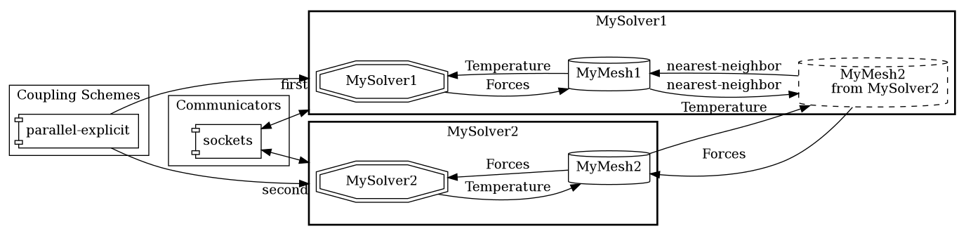
The configuration consists, in general, of the following five parts:
<precice-configuration>
  <data .../>
  <mesh .../>
  <participant .../>
  <m2n .../>
  <coupling-scheme .../>
</precice-configuration>
1. Coupling data
You need to define which data values the coupled solvers want to exchange, e.g. displacements, forces, velocities, or temperature.
<data:scalar name="Temperature"/>
<data:vector name="Force"/>
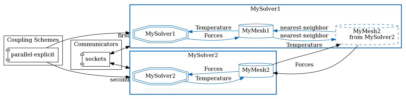
2. Coupling meshes
Next, you can define the interface coupling meshes.
<mesh name="MyMesh1" dimensions="3">
  <use-data name="Temperature"/>
  <use-data name="Forces"/>
</mesh>
The value dimensions needs to match the physical dimension of the mesh, i.e. the number of coordinates a vertex has in setMeshVertex, etc. Some solvers only support 3D simulation, such as OpenFOAM or CalculiX. In this case the adapter maps from 3D to 2D if the mesh dimension is 2D. This, of course, only works if you simulate a quasi-2D scenario with one layer of cells in z direction.
3. Coupling participants
Each solver that participates in the coupled simulation needs a participant definition. You need to define at least two participants.
<participant name="MySolver1">
  <provide-mesh name="MyMesh1"/>
  <read-data name="Temperature" mesh="MyMesh1"/>
  <write-data name="Forces" mesh="MyMesh1"/>
  ...
</participant>
The name of the participant has to coincide with the name you give when creating the participant object in the adapter:
precice::Participant precice("MySolver1", "precice-config.xml", rank, size);
The participant provides the mesh. This means that you have to define the coordinates:
precice.setMeshVertices("MyMesh1", coords, vertexIDs);
The other option is to receive the mesh coordinates from another participant (who defines them):
<receive-mesh name="MyMesh2" from="MySolver2"/>
If a participant uses at least two meshes, you can define a data mapping between both:
<mapping:nearest-neighbor direction="read" from="MyMesh2" to="MyMesh1" constraint="consistent"/>
nearest-neighbor means that the nearest-neighbor mapping method is used to map data from MyMesh1 to MyMesh2.
Read more about the mapping configuration.
4. Communication
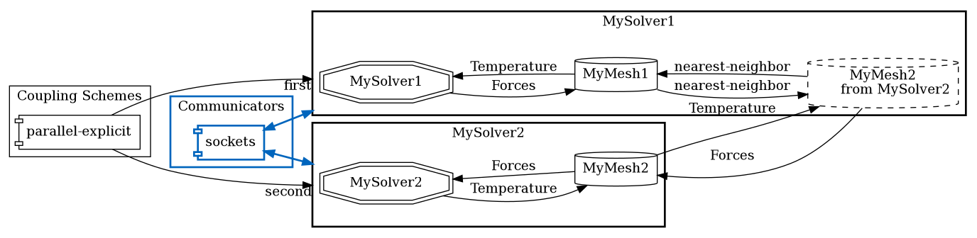
If two participants should exchange data, they need a communication channel.
<m2n:sockets acceptor="MySolver1" connector="MySolver2" />
Read more about the communication configuration.
5. Coupling scheme
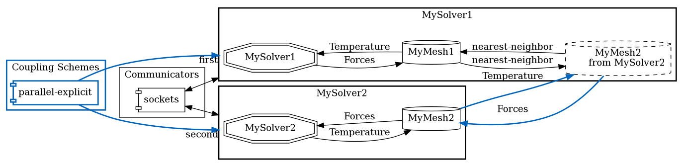
At last, you need to define how the two participants exchange data. If you want an explicit coupling scheme (no coupling subiterations), you can use:
<coupling-scheme:parallel-explicit>
  <participants first="MySolver1" second="MySolver2"/>
  <max-time value="1.0"/>
  <time-window-size value="1e-2"/>
  <exchange data="Forces" mesh="MyMesh2" from="MySolver1" to="MySolver2"/>
  <exchange data="Temperature" mesh="MyMesh2" from="MySolver2" to="MySolver1"/>
</coupling-scheme:parallel-explicit>
parallel means here that both solver run at the same time. In this case, who is first and second only plays a minor role. max-time is the complete simulation time. After this time,
precice.isCouplingOngoing()
will return false. The time-window-size, is the coupling time window (= coupling time step) length. This means if a solver uses a smaller time step size, he subcycles, i.e. needs more smaller time steps until data is exchanged.
Both participants need to either provide or receive the mesh over which data is exchanged (here MyMesh2).
For implicit coupling, i.e. both solver subiterate in every time window until convergence, the configuration looks a bit more complicated.
Read more about the coupling scheme configuration.